|
|
|
Who's Online
There currently are 5820 guests online. |
|
Categories
|
|
Information
|
|
Featured Product
|
|
|
 |
|
|
There are currently no product reviews.
 ;
Very good quality scan of the document. I am very pleased with what I got.
;
PDF Contains
Technical Data, Mechanical data, Detailed Circuit diagram with components value, PCB layout. Actual PCBs Print. Component List, Spare parts code list and Input output detail. It cover LBB1211, LBB1212, LBB1213, LBB1216, LBB1217.
It is the actual Service Manual for SQ10
;
very good manual with clear electrical schemes. Very helpful to find wat was wrong inside my microwave.
 ;
Hi, thankyou for providing the Nordmende Globetrotter original manufacturer's repair manual. Quality is very good and sharp - the PDF file was comfortably small to download. The only question is: why did it take so long to become ready for download?? Many thanks anyway, I fixed the fault in the radio thanks to the circuit.
regards: Nick
;
This was super service.Ordered this manual and was reading the download an hour later
HCD-CL1/CL3
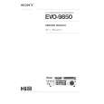
Note : Clear RF signal waveform means that the shape � � � can be clearly distinguished at the center of the waveform.
Adjustment Location: [BD (CD) BOARD] (Conductor Side)
RF signal waveform VOLT/DIV : 200mV TIME/DIV : 500ns
level : 0.65 ±0.15Vp-p (RFDC) 1.1 ±0.4Vp-p (RFAC)
E-F Balance (1 Track jump) Check
BD (CD) board TP(TEO) TP(DVC) oscilloscope
TP (DVC) TP (RFAC) 15 1 IC103 16 30 TP (FEO) TP TP (TEO) (FEI)
21 20
40 41
IC101
1 80
Procedure : 1. Connect an oscilloscope to TP (TEO) and TP (DVC). 2. Turn Power switch on. 3. Load a disc (LUV-P01) and playback the number nine track. 4. Press the gG button. (Becomes the 1 track jump mode.) 5. Confirm that the level B and A (DC voltage) on the oscilloscope waveform.
1 track jump waveform center of waveform B A (DC voltage) DVC level=1.0 ±0.5Vp-p symmetry
TP (RFDC)
60 61
RV101
6. Adjust RV101 on the BD board so that the center of waveform becomes the same voltage of DVC. (i.e. A=0V)
20
|
|
|
> |
|